Professional Work:
Jetoptera
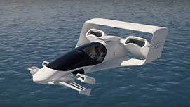
Jetoptera is a startup creating Vertical Take Off and Landing (VTOL) transportation vehicles which use a unique propulsion system, called FPS. Jetoptera is developing several vehicles using this technology from small UAVs to full-scale flying cars. Originally, I joined Jetoptera for an internship in 2019 and returned after graduating in the role of Lead Engineer.
As lead engineer, I oversaw 4 externally funded programs aimed to further demonstrate Jetoptera’s technology. The programs included: acoustic wind tunnel testing of Jetoptera’s propulsion system, creation and testing of novel flap design, and wind tunnel testing of a novel VTOL aircraft model. As lead engineer, I led execution of these projects, including: defining project scope and deliverables, maintaining project schedule, managing contracted engineers, directing test article design, working with manufacturers to produce models, interfacing with engineering teams to assemble models, and leading testing efforts. Additionally, I completed mechanical design such as: model structure design, compressed air routing, dynamic seal design, measurement and instrumentation design, and propulsion system design.
In addition, I led Jetoptera’s internal efforts across many projects, engineering and otherwise. I completed design and organized tests to utilize Jetoptera’s propulsion system on watercraft, completed integration and aircraft design for smaller UAVs, and developed CAD models for conceptual aircraft designs. Additionally, I completed other tasks such as designing a trade show model, creating investor presentations, and helping with funding proposals. Because Jetoptera is a startup, I gained experience in many different aspects of engineering and business. I learned what it takes to lead engineering efforts to a timely and successful completion and how those efforts contribute to the ultimate success of the company.
Blue Origin
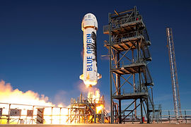
At Blue Origin, I improved the testing process for pneumatic valves used by Blue Origin’s BE-3 and BE-4 rocket engines. Specifically, I made a test bench that allows for faster and simpler testing of these valves. I looked at test procedures, talked to technicians, and communicated with engineers to determine the best test configuration. After determining the test setup, I created the test bench. This included designing and building both a control panel and a test chamber for the valves. The control panel allowed for easy and rapid testing of different test types and configurations. I included pressure systems, cryogenic systems, and more. All of this allowed testing of valves for the engines to be done in a significantly faster and easier fashion.
In addition to my main project, I also asked for additional work to gain experience in other areas of Blue Origin. This included conducting material testing relating to the BE-4 engine, vacuum testing for other valves, and electronic harness design. I also reviewed part drawings and updated manufacturing work instructions for some of the pneumatic valves.
Working at Blue gave me experience in a high-quality aerospace company and introduced me to many of the systems, procedures, and processes that lead to high quality, high reliability engineering. I learned significant amounts about the manufacturing engineering process, and how to create parts and systems when high degrees of safety are required and system critical. I also became more ambitious, self-driving, and passionate. Working at Blue was a great experience that fueled my interest in the aerospace industry.
MITRE:
I spent the summer of 2018 as a drone design intern at MITRE. I designed and built a quadcopter that leverages 3D printing technology and consumer-off-the-shelf (COTS) electronics. I designed and built this lightweight surveillance quadcopter specifically for the needs of one of MITRE's sponsors. The drone is built to provide surveillance, reconnaissance, and situational awareness in hazardous situations. Critical sponsor requirements for this project were making the drone lightweight, easily packable, quickly deployable, and easily replaceable. To meet these requirements, I used modular 3D printed pieces that allowed the drone to be easily assembled and repaired in any situation. Additionally, I designed parts to minimize build time, allowing for more quadcopters to be built. My final product was a drone weighing only a few pounds that utilizes folding arms to allow it to fit in a standard backpack and be rapidly deployed. I obtained my commercial drone license (Part 107) and performed flights tests, discovering that the drone was incredibly stable and extremely fast.
To facilitate ease of assembly, I created guides to allow for assembly and flight with little to no prior training, allowing the sponsor to produce the quadcopter in mass quantities. When designing, I also kept failure modes in mind, intentionally crafting the quad's weakest points to be in easily replaceable, small pieces, allowing operators to carry extra pieces and quickly repair the quad in case of a crash. At MITRE, I significantly improved my ability to develop technical products and meet specific guidelines.
Novo Nordisk:
At Novo Nordisk, I worked to inform a design decision for the team to help determine their path forward in their early R&D efforts. While the sensitive nature of my project prevents me from specifically describing my work, I was tasked with researching a new and rapidly rising field and determining whether that technology could be constructively implemented into their long-term project.
I started by becoming familiar with the technology. I dove deeply into the details of this field, reading articles, technical papers, and scoured company websites, keeping track of potential solutions as I went. Once I thoroughly understood the field, I documented the strengths and weaknesses of various sub-fields of this technology. From there, I focused on the sub-fields whose strengths matched the requirements of our project. I contacted companies, creating a detailed catalog of the products in this field. After this, I ordered some of the existing technologies and measured their capabilities. I then created prototypes that would allow these products to interface with ours. These prototypes included mechanical and electrical components, including 3D printing. After assembling my prototypes, I measured their performance and compared it against the project requirements.
I left my team with a prototype and list of technologies, companies, and products to watch as this field continues to grow so that they may find a great use for this technology soon. This project improved my research, prototyping, and communication skills.
Formula SAE
Overview:
I worked as a member of the transmission team for Olin’s Formula SAE team: Olin Electric Motorsports. In Formula, I designed low tolerance parts that smoothly interacted with other systems and could withstand large forces, teaching me high-quality CAD practice, in-depth force analysis, design for manufacture, and overall system design. Formula SAE brought me into the world of industry-grade engineering.
Transmission Team:
When I first joined Olin Electric Motorsports, I decided to join the transmission sub-team. In my first year, I worked on many parts of the transmission. Specifically, I worked with another student to design our differential and its interface with the rest of the car. We took the internals from a Torsen differential and built a custom housing and carrier for it. This design was cheap, easier to seal, and was significantly lighter than the stock differential. After we finished designing the differential housing and carrier, we manufactured it and began working on other parts of the transmission system. This included choosing components such as the car’s motor and stub shafts and designing the transmission clock cage.
The following year, I worked to redesign the transmission mounting to be lighter, more easily accessible, and provide convenient chain tensioning capabilities. I designed and created a SOLIDWORKS model of the differential mount and conducted finite element analysis using ANSYS to validate the strength of the differential and motor plates. We then fabricated this assembly and put it into our vehicle.
FIRST Robotics:
Overview:
During high school, I participated extensively in FIRST Robotics. With fewer than 10 committed members, my team was extremely small, allowing me to quickly become an integral part of the team. Averaging more than 6 hours a day in robotics during the 3 month build seasons, I quickly integrated FRC, and engineering, into my life.
Personal Work:
In robotics, I participated in the design, prototyping, and manufacture of every major system of the robot for two years. While on the team, I played every role from team member to vice president. While in these roles, I participated heavily in robot design, created CAD models, manufactured parts, prototyped parts, performed analysis, advised younger members, coordinated club activities, led teams of members from system design to final manufacturing, led design reviews, and more. In robotics, I got to work on every part of the engineering process, which was an amazing experience that gave me extensive knowledge across every system of the robot, forcing me to understand how every aspect of each system function and interacted.
Summary:
My favorite part of FIRST was the rapid prototyping aspect. As a senior member of the team, I had the expertise to be one of our team’s rapid prototypers. On our 2016 robot, I demonstrated the feasibility of the systems that collected balls, shot balls, moved balls through our robot, and actuated the robot’s arms. This was extremely rewarding, as I was able to push our designs to the next phase by showing feasibility.

Source: jetoptera.com

Source: mitre.org


Projects, Schoolwork, and Personal Development
Odysseus
Overview:
During my sophomore year at Olin, I worked with 4 team members to create Odysseus: a CNC lathe/mill. Odysseus, our final product for our Principles of Engineering class, has 3 axes of freedom which it uses to rotate stock and move a rotary tool vertically and horizontally. Based on this movement, it combines functionality of a lathe and mill to create 3D CNC parts.
Mechanical:
As a member of the mechanical team for this project, I participated heavily in the design and manufacture of many parts of the system. Specifically, I designed and built the horizontal assembly which houses the Dremel and moves it towards and away from the stock using a lead screw. The housing is made of laser cut MDF and holds the Dremel with 3D-printed parts. I also participated in the design and fabrication of the chuck and the design of our final housing, which includes a vacuum attachment to remove chips, and a Plexiglas shield to protect observers.
Software and Electrical:
Odysseus uses an Arduino to control the 3 stepper motors to cut the stock over a series of passes. On the software side, I wrote code to allow Odysseus to be controlled with a joystick. This allows us to set the origin for our part without manually turning the lead screws. Besides providing power for our motors, our electrical system includes an emergency stop, and magnetic door switch to improve the safety of our product.
Watch a video here
Quadcopter:
Overview:
While at Olin, I created my own quadcopter. As I had always been interested in quadcopters, but had never had the opportunity to fly one, I took it upon myself to build my own. I knew very little about quadcopters before starting this and learned a lot, making it fun and worthwhile.
Electronics:
To aid in my learning, I designed my own electronics system. I found a lot of the information for required components online and designed my system using the knowledge that I gained. I purchased my motors, motor controllers, transmitter, and flight-controller and assembled the system.
Mechanical Design:
I then designed the mechanical system. After creating the system in SOLIDWORKS, I chose to 3D print the base and laser cut the top. For the quadcopter’s arms, I took aluminum extrusions and drilled out holes for the motor mounts which are off-the-shelf carbon fiber mounts. The design fits together well and has allowed the quad to fly beautifully. Despite many crashes (due to pilot error as I learned to fly) the quad has continued to fly and perform well.
I completed further iterations of quadcopters incorporating FPV into my projects and have since continue to fly. Building quadcopters has helped me learn about wiring harness design and mechanical design.
DORS:
Overview:
During my senior year of high school, I worked with 4 peers to design and begin fabrication of a submersible to collect water quality data on water Ph., dissolved oxygen quantity, conductivity, pressure, turbidity, and more. The goal of this project was to augment the Department of Ecology’s databases.
Rudder System:
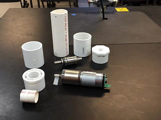
I designed and built the rudder system that would drive the submersible. The rudder system used a ruddervator design, consisting of 4 separate rudders. Each rudder was powered by a PG-188 motor mounted on 3D printed pieces inside of a PVC casing. The casing needed to be waterproof to depths of 100 feet, so I used a waterproof bearing from a car’s water pump to seal the housing. To transmit torque between the motor and the rudder shaft, I designed and machined couplers for the interfaces between the PG-188 and the waterproof bearing and the waterproof bearing and the rudder shaft.
Geared Tethering System:
I designed a system to tether the submersible to a buoy that would relay communication data. I calculated the required gearing ratio and found gears that would provide it. I also chose constant force springs to tension a 100-foot tether and keep the tether from unspooling and ensnaring the submersible.
Electrical System Enclosures:
I also designed and built the system to house the electrical enclosures while the submersible was underway. I used barbed fittings to connect plastic tubing between store-bought waterproof boxes. This allowed me to connect the battery enclosure to the electronics housing and motor. I tested the housing using compressed air and found it to hold pressures at depths equivalent to 100 feet. After graduating, we passed this project to students from the following year.
Mechanical Design
Overview:
This was a class at Olin focused on mechanical design including instruction on part design, Solidworks modeling, design for manufacture, FEA, and assembly drawings.
Mechanical Design and Modeling:
Projects for this class involved replicating designs of interesting mechanical systems in high fidelity Solidworks models. Using pictures of the models as a reference, I created detailed assemblies, down to detailed aspects such as fasteners and pins. During the class, I completed assemblies of a mechanical claw, unmanned ground vehicle (UGV), transportable interoperable ground vehicle (TIGR), and much more. Completing designs of these systems helped me learn about mechanical design features such as linkages, belts, gears, sprockets, fasteners, pins, and more.
Analysis and Part Drawings:
Once the CAD models of these systems were completed, I conducted further analysis of these assemblies. I identified potential loads for the systems and conducted finite element analysis on critical system components. I redesigned components that did not meet a sufficient factor of safety and refined the model based on the findings. After completing FEA, I created detailed part drawings and assembly drawings for the model. Completing this project significantly increased my ability to design and analyze complex mechanical systems and create detailed drawings.
3D-Scanner
The 3D-scanner was a quick project for one of my classes. The goal was to use an IR sensor to record distances at numerous different points in order to create a map of a three-dimensional space.
Before recording data, I needed to calibrate the IR sensor to map the input data the Arduino received to real distances. To do this, I took measurements from the IR sensor at many different distances and then did a polynomial fit in MATLAB to find the equation that mapped the sensor data to real distances.
As the IR sensor had a very limited range of sight, it needed to be moved to various positions to collect data points in the entire 3D-space. To do this, I used two servos to pan and tilt the sensor. I wrote an Arduino program that controlled the servos, taking data points every few degrees in both the horizontal and vertical directions.
After this, I wrote a function that would take the Arduino data and import it into MATLAB. Then, I used MATLAB to calculate the horizontal distance of each data point based on the pan and tilt angle of the sensor when it was taken. After this, I graphed the data on both a 3D plot and a heat map.
EncryptIT
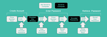
Encrypt it is a software program that I worked on for our software design class. We started by learning about encryption and the different types that are used in industry systems. After learning more, we decided that a good project to demonstrate our encryption abilities would be to create a password manager that would allow you to create a profile and store encrypted passwords.
We continued to research more about encryption and discovered that RSA encryption is a common industry-grade encryption method. I continued researching and wrote a program that was able to conduct RSA encryption to protect a user's passwords. We then created a full password protection system around this. The system was based around user accounts. Each user account would be unlocked by a password, which we stored in our system after hashing, a one way encryption process. When the user logs in again, they will re-hash the new password and will only gain access if the passwords match. When an account is created, we generate a unique prime number with which we do RSA encryption to protect their stored passwords. However, to avoid saving the prime numbers in our database, we XOR the users password with their prime number to create an encipher key which we can store in our database. To retrieve the password, we simply XOR the encipher key with the password again and undo the RSA encryption.
After we finished our encryption portion, we decided to create a website that would allow you to store and access your passwords online.
User Design
User Oriented Collaborative Design (UOCD) is a unique design class taught at Olin. The purpose of the course is to teach students how to design with their stakeholders, allowing them to create highly relevant and useful products and services. The class pairs a group of students with a "user group", and the group spends the entire semester working with this group with the end goal of creating a product, service, or other idea that will be beneficial to them.
My group choice to work with service, therapy, and emotional support animal trainers over the course of the semester. Over the course of the semester we met with over 15 trainers and learned an incredible amount about their lifestyles. We learned that some of the biggest problems they face are a lack of awareness from the general public, a lack of volunteers, and a lack of funds. After learning how selfless and impactful these trainers truly are, we wanted to come up with a useful idea that would change their lives.
We spent weeks ideating and communicating our ideas to members of the service dog community. Finally, we found an idea that was productive to the group that they were passionate about. Our idea was a traveling awareness campaign that would show up in cities across the country, promoting the usefulness of trainers. This was a great design experience as it allowed us to understand that the products and services that users really need are more complicated than we would normally expect.
Electric Motor
At Olin, I took a student-led class called Intro to Electric Vehicle Design. As a final project for this class, two other students and I decided to build a very basic electric motor to better understand how electric motors work. To start, we researched electric motors.
After we understood electric motors, we had to decide what would be an accurately scoped project. We determined that we would try to create the basic functionality of an electric motor with simple components.
We used bolts wrapped with insulated copper wire to create the stator for the motor and used a magnet inside of a 3D printed case for the rotor. We assembled all of this in a 2-part 3D printed housing that clamped the bolts in place and held a bearing for the magnet to rotate on. Then, we focused on controlling it. One of the members of our team made an electrical circuit that would run current through the bolts in the proper direction, and I wrote an Arduino program and wired it to the circuit to make it work properly.
After all this, we connected the motor to the circuit. While we were unable to get the motor to spin fully as our coils were not strong enough to overcome the magnetic attraction to the bolts, we were able to get the magnet to twitch back and forth, demonstrating how an electric motor works.